WARNING
Tube amplifiers operate at high voltages which may cause property damage, serious injury or death. Proceed at your own risk. The content on this website is intended for informational purpose only.
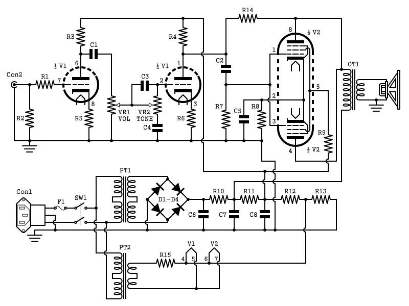
2W Tube Guitar Amp Schematic
A brief description and design goals for the 2W Tube Guitar Amp can be found here.
 2W Tube Guitar Amp Schematic
Schematic
The 2W Tube Guitar Amp Schematic is also available as a PDF file with bill-of-material (BOM).
Circuit
The 12L8GT Output Tube
A word about the chosen output tube may be in order. The 12L8GT is an Octal base, twin-pentode designed for low power output audio use. Plate dissipation is only 2.5W per unit. In fact, most applications of this tube were in communication receivers and radios, many in the military.
The two pentodes in the 12L8GT have their screens (G2) internally connected, as well as their Cathodes. For this design I choose to wire the two halves in parallel, similar to an early Gibson "Gibsonette". A spec sheet can be found here (will open in a new window). I believe the two Pentodes in parallel adds low-order harmonics for an even sweeter tone.
Not a terribly sensitive tube, such as the EL84, it is still biased to only 7.6V using a bypassed Cathode resistor of 270 Ohm. Any signal with a peek over 7.6V will overdrive the output stage. So early breakup is on the menu.
Output Transformer
The output transformer I used for the prototype is the Edcor XSE10-8-5k. The two Pentodes in the 12L8GT wants to see a load of 10k each, being connected in parallel, total load impedance should be 5k at whatever load your speaker cab presents. In my case the speaker is 8 Ohm.
Negative Feedback
Negative Feedback is a way to increase bandwidth and reduce distortion at the price of some gain. The main purpose I use it, and in particular in this amp, was to dump some gain. I introduced a "Shade resistor" (R14 = 1MOhm) between the plate of the output tubes and preceding triode. Before the resistor was added the output stage was overdriven when the gain was at 9 o'clock with moderately weak Strat type single coil pickups. After the Negative Feedback resistor was installed it overdrives with the volume at 12-noon.
Pre Amp
The pre-amp is a very common design utilizing the well known 12AX7 (ECC83) dual triode tube. Originally lifted from the RCA Radiotron Handbook by Leo Fender himself, the basic circuit can be found in radios, film projectors, PA amps, reel-to-reel tape recorders, intercoms from the 40s and 50s. It can also be found in amps such as the previously mentioned Gibsonette and Fender Tweed Princetons (5F2) and a whole host of practice amps of the same time period.
Tone Stack
The tone stack is the same "no frills" single tone knob you would find on the Fender Princeton 5F2. Back to basics, baby.
Definitely not my favorite as it is impossible to dial in a flat response. I much prefer the James (sometimes incorrectly called Baxandall) tone stack. It has a Bass and a Treble knob and can be dialed to a flat response. The reason I went with the single knob in this design was due to space constrains (See link to main project page for this amp for more, link above).
Power Supply
The power supply consists of two mains transformer. One is a 12.6VAC for heater supply. I had to add a resistor in series to bring the voltage within spec for the tubes chosen.
The High Voltage Transformer (HV) is a common 120-to-120VAC isolation transformer. After a bridge rectifier made up of four 1N4007s and first filter stage, the B+ maintains 172VDC. Both power transformers used in this amp are Hammond Brand.
In the schematic a voltage divider can be seen (resistor R12 & R13). Their purpose is to elevate the heater voltage to approximately half of B+. This step reduces hum in the amp to virtually zero.
Recent Articles
-
Speaker Plans
Feb 04, 18 05:23 PM
Speaker plans for download - free pdfs for DIY builders and tire kickers
